

Quick Start Guide Hub and Node
Disclaimer: The user is required to observe and adhere to the currently applicable instruction manuals for all Vemaventuri products utilized.
01 Preparation
Step 1: Unboxing
Welcome to your Hub and Nodes!
Inside the box, you’ll find:
- 1x Hub
- 2x Nodes
- 2x EU power adapters
- 2x Charging Cables with PERI bus connection
.jpg?width=800&height=569&name=1%20(2).jpg)
Depending on the application, the package may also include:
- PREMO Set
- TEMO Set
- PHONO Set
.jpg?width=800&height=569&name=2%20(4).jpg)
Step 2: Charge the Devices
Before operation, ensure that both the ISC Hub and all ISC Nodes are sufficiently charged.
The current battery status can be checked either on the device display or by observing the LED indicators on the unit.
.jpg?width=800&height=569&name=3%20(3).jpg)
For the ISC Node, briefly press the function button:
- All four LEDs should illuminate.
- If fewer than four LEDs light up, recharge the node before use.
02 Setup & Configuration
Step 3: Switch On the ISC Hub
- Press and hold the ON/OFF button on the ISC Hub.
- Release the button when the device starts up and the display lights up.
- The ISC Hub is now switched on and ready for operation.
.jpg?width=800&height=569&name=4%20(3).jpg)
Step 4: Select Language
- After powering on the device, you must first select a language.
.jpg?width=800&height=569&name=5%20(1).jpg)
- You will then be redirected to the project setup screen.
- To create a new project, click on "New Project" at the bottom of the screen.
.jpg?width=800&height=569&name=6%20(2).jpg)
Step 5: Scan the QR Code
Either scan the QR code shown on screen, enter the URL displayed on the screen, or simply click the URL (https://insite.peri.app/c) to continue and follow the on-screen instructions.
The serial number can be found on the back of the device under S/N.

Step 6: Sign In & Confirm Device
- Click “Sign in with PERI.”
- Don’t worry about being redirected — our web platform uses the same secure technology as the central PERI customer portal for a seamless experience.
- Log in with your credentials or click “Sign up now” to create a new account.


- After signing in, your Hub will automatically appear in the WebApp when using the QR code. If you are using the link instead, enter the serial number found on the back of the device.
- Once verified, click “Next” to finalize the connection process.
.jpg?width=450&height=633&name=8%20(3).jpg)
Step 7: Select or Create New Project
- Select existing project: If you’ve already created a project in the Web App, select it from the list.
- Create new project: If this is your first setup, select this option to create a new project. You can name your project and define its details in the next step.
Step 8: Complete Project Setup
Finalize your project setup by entering the required details:
- Project & Customer: Add a project name, company name, and (optional) customer or concrete catalog.
- Location: Enter the project address, weather forecast city, and select the correct timezone.
- Measurement Units: Choose Metric, Imperial/US, or Custom and define your preferred units.
.jpg?width=400&height=563&name=7-5%20(1).jpg)
.jpg?width=400&height=563&name=7-6%20(1).jpg)
After entering all required information, tap "Next". The device will then automatically configure itself. Please wait until the process is completed.


Step 9: Pairing the Node with the Hub
After the project has been created, you will be automatically taken to the Node Pairing menu.
Note: A Node can only be paired while you are in the Node Pairing menu.
.jpg?width=800&height=569&name=9%20(1).jpg)
- Turn on the Node by pressing and holding the On/Off button until all LEDs light up.
.jpg?width=800&height=569&name=11%20(1).jpg)
- When the LEDs are blue, press the button three times to start the pairing process.
- When pairing is successful, the Node returns to normal operation and the LEDs indicate the current status.
- Once pairing is complete, a notification will appear on the Hub confirming that the Node has been successfully paired. You can now pair additional Nodes if needed.
.jpg?width=800&height=569&name=12%20(2).jpg)
- Once all Nodes are paired, the setup is complete and the Hub is ready for measurements.

03 Concrete Temperature and Maturity Monitoring
Follow this section if you are monitoring concrete temperature and maturity.
Set up the measuring points
Watch the video or follow the steps below:
Cut off the required length of cable from the thermocouple roll.
1) Strip the outer insulation
Remove the outer insulation on both ends of the cable with the wire stripper to expose the two inner conductors.
2) Strip the inner conductors
Strip approximately 12–15 mm of insulation from each of the two inner wires.
3) Twist the conductors
Side A: Twist the two inner conductors individually.
Side B: Twist the two inner conductors together into one combined twisted end.
4) Apply heat-shrink on Side B
Slide a heat-shrink tube over the combined twisted end on Side B and shrink it with a lighter until it is tight and secure.

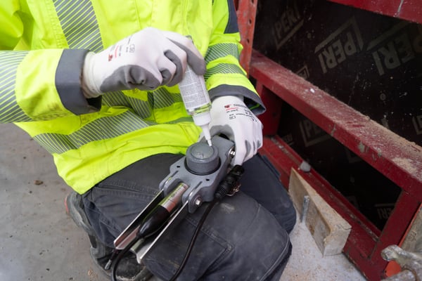
Connect the thermocouple to the Node
- Loosen the terminal screw until the stripped wire end can be wrapped once around the threaded bolt.
- Attach the brown wire to the brown (+) terminal.
- Attach the white wire to the white (–) terminal of the same channel.
- Ensure that only one thermocouple is connected to each channel.
Fix the Measuring Point Inside the Formwork
Place the heat-shrinked cable end at a suitable measuring point inside the formwork and secure it firmly to the reinforcement with a cable tie so it cannot move.
Note: Ensure the cable is not pinched or trapped between rebar layers.
Tip: Mark each device with a sticker and document both its position and the thermocouple positions—this will make the web app setup much easier later on.
.jpg?width=800&height=569&name=12%20(1).jpg)
Concrete Maturity Measurement (Optional)
If you want to measure concrete maturity, the concrete must be calibrated in advance.
Calibration is not part of this Quick Start Guide.
Please refer to the Quick Start Guide - Concrete Calibration for detailed instructions.
04 Concrete Pressure Monitoring
Follow this section if you are monitoring concrete pressure.
Preparation
- Check the sensor, cable, connector, housing, and membrane for damage
- Make sure the sensor is free of air bubbles
- Prepare the required tools:
- Drill
- 50 mm hole saw with centre drill
- Screws
- Grease (e.g. Vaseline)
Installing the Sensor
- Drill the hole: Drill a 50 mm hole into the formwork using the hole saw.
→ Ensure there is enough space for the sensor housing.
- Grease the sensor: Lightly grease the membrane and housing (recommended: Vaseline)
- Position the sensor: Place the sensor on the formwork and pre-drill the screw holes.
- Fix the sensor: Secure the sensor with 3 screws.

Connection & Start-up
- Mount the Node: Fix the Node safely and securely near the sensor.
- Connect the sensor: Connect the sensor to the PERI bus connection of the Node.
- Switch on the Node: Measurement starts automatically.
- Documentation: Record the Node number and the sensor position or installation height.
Note: Determine and mark the positions of the sensors.
– The distance between the sensors should be approx. 1.5 m for an 8-m-high wall.
– Position the sensors in the lower part of the formwork.
– An additional series of sensors will increase the accuracy.
%201.png?width=400&height=605&name=Pressure_XLR_config1%20(1)%201.png)
Note: A separate Quick Start Guide – Maintenance is available, providing detailed instructions for membrane replacement, glycerol refilling, and venting.
05 Concrete Detection and Compaction Monitoring
Follow this section if you are monitoring concrete detection and compaction.
Preparation
- Check the sensor head and cable for any visible damage.
- Prepare suitable mounting materials, such as cable ties, adhesive bases, adhesive tape, and an appropriate adhesive (e.g. epoxy glue).
Sensor Installation
- Select a suitable measuring point: The substrate must be clean, smooth, and robust, e.g. form lining, rock, or concrete.
- Remove the protective film: Remove the protective film from the adhesive surface of the sensor.
- Fix the sensor in place: Press the edges of the sensor firmly onto the substrate.
Important: Do not apply pressure to the sound element in the center of the sensor. In cold temperatures, warm up the adhesive surface before fixing to improve adhesive strength.
If the adhesive strength of the double-sided adhesive surface is not sufficient (e.g. on rough or uneven substrates), apply additional adhesive.
The sound element must remain completely free of adhesive. Alternatively, the sensor can be attached to the reinforcing steel using cable ties and an adhesive base. - Route the cable: Lay the cable securely inside the formwork and fix it using cable ties or adhesive tape.

Connecting to the ISC Node
- Mount the ISC Node: Install the ISC Node close to the measuring point, outside the formwork, in a safe and secure position.
- Connect the sensor wires: Connect the sensor wires to an analogue multifunction channel of the node:
- Unscrew the pole terminal until the stripped wire end can be wrapped once around the threaded bolt.
- Connect the black wire to the brown terminal (+).
- Connect the red wire to the white terminal (–) of the same channel.
- Only one vibration sensor may be connected to each pair of terminals or channel.
- Tighten the terminals: Screw the pole terminals back on and tighten them hand-tight.
.jpg?width=500&height=667&name=IMG_0048%20(1).jpg)
Start Measurement
- Switch on the node: Measurement data from the connected sensors is received automatically.
- Switch on the ISC Hub.
- Documentation: Record the node number and the corresponding channel for each sensor.
06 WebApp
Step 9: Create Dashboards and Reports in the WebApp
Open your project in the web app and create a dashboard. To display measurements in your dashboard, add a new widget by clicking “+ Add measurement” in the desired section. Follow the on-screen steps to link your device to the widget.
To create a report, click “Configuration” and scroll down to the Reports section.
Note: If measurements are not visible, check the selected date range and verify your device’s connectivity.
