

Quick Start Guide ISC Link
Disclaimer: The user is required to observe and adhere to the currently applicable instruction manuals for all Vemaventuri products utilized.
01 Preparation
Step 1: Unboxing
Welcome to your ISC Link!
Inside the box, you’ll find:
1) 4x ISC Link
2) 2x USB-C charging cable
.jpg?width=800&height=569&name=1%20(1).jpg)
Depending on the application, the package may also include:
3) Pressure Sensor Set
4) Digital temperature sensors
.jpg?width=800&height=569&name=2%20(3).jpg)
Step 2: Charge the Device
Before getting started, we recommend fully charging your ISC Link.
Use the included USB-C cable to connect it to a suitable power source.
.jpg?width=800&height=569&name=4%20(2).jpg)
02 Setup & Configuration
Step 3: Power On the Device
- Turn on the ISC Link device by pressing and holding the ON/ OFF button for three seconds.
- Device LED blinks green
Note: If the device has been connected to a previous project:
1. Turn on the device.
2. Press the ON/OFF button once.
3. Wait until the green LED turns on.
4. Quickly press the button 4 more times to make the LED blink green.
.jpg?width=800&height=569&name=3%20(2).jpg)
Step 4: Scan the QR-Code
Either scan the QR code shown on the back of the device, enter the URL displayed on the screen, or simply click the URL (https://insite.peri.app/c) to continue and follow the on-screen instructions.
The serial number can be found on the back of the device under S/N:.
Step 5: Sign In
- Click “Sign in with PERI.”
Don’t worry about being redirected — our web platform uses the same secure technology as the central PERI customer portal for a seamless experience. - Log in with your credentials or click “Sign up now” to create a new account.


Step 6: Confirm Device
- After signing in, your TEMO Link will automatically appear in the WebApp when using the QR code. If you are using the link instead, enter the serial number which you find on the back of the device.
- Once verified, click “Next” to finalize the connection process.
.jpg?width=450&height=633&name=8%20(2).jpg)
Step 7: Select or create new project
- Select existing project:
If you’ve already created a project in the Web App, select it from the list. - Create new project:
If this is your first setup, select this option to create a new project. You can name your project and define its details in the next step.
Step 8: Complete Project Setup
Finalize your project setup by entering the required details:
- Project & Customer: Add a project name, company name, and (optional) customer or concrete catalog.
- Location: Enter the project address, weather forecast city, and select the correct timezone.
- Measurement Units: Choose Metric, Imperial/US, or Custom and define your preferred units.
.jpg?width=380&height=534&name=7-5%20(1).jpg)
.jpg?width=380&height=534&name=7-6%20(1).jpg)
After entering all required information, tap "Next". The device will then automatically configure itself.
Please wait until the process is completed.


03 Concrete Temperature and Maturity Monitoring
Follow this section if you are monitoring concrete temperature and maturity.
Installing and Connecting Temperature Sensors
Each channel (CH-A and CH-B) on the ISC Link supports one temperature sensor.
To install and connect a temperature sensor, follow these steps:
- Plug the connector of the temperature sensor into CH-A or CH-B on the ISC Link.
.jpg?width=800&height=569&name=6%20(1).jpg)
- Place the measuring tip at the desired measurement location.
- Secure the sensor in position, for example by attaching it to the rebar using cable ties.

Concrete Maturity Measurement (Optional)
If you want to measure concrete maturity, the concrete must be calibrated in advance.
Calibration is not part of this Quick Start Guide.
Please refer to the Quick Start Guide - Concrete Calibration for detailed instructions.
04 Concrete Pressure Monitoring
Follow this section if you are monitoring concrete pressure.
Note: Determine and mark the positions of the sensors.
– The distance between the sensors should beapprox. 1.5 m for an 8-m-high wall.
– Position the sensors in the lower part of the formwork.
– An additional series of sensors will increase the accuracy.
Preparation
- Check the sensors, cables, connectors, housings, and membranes for damage
- Make sure the sensors are free of air bubbles
- Prepare the required tools:
- Drill
- 50 mm hole saw with centre drill
- Screws
- Grease (e.g. Vaseline)
Installing the Sensors
- Drill the hole
Drill a 50 mm hole into the formwork using the hole saw.
→ Ensure there is enough space for the sensor housing
- Grease the sensor
Lightly grease the membrane and housing (recommended: Vaseline).
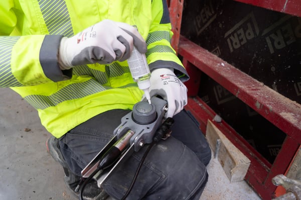
- Position the sensor
Place the sensor on the formwork and pre-drill the screw holes. - Fix the sensor
Secure the sensor with 3 screws.
- Connect the sensors
Use the XLR cables to connect the sensors.
Connection & Start-up
- Mount the ISC Link
Fix the ISC Link safely and securely near the sensor. - Connect the sensor
Connect the sensor to the CH-A or CH-B connection of the ISC Link. - Switch on the ISC Link
Measurement starts automatically. - Documentation
Record the ISC Link number and the sensor position or installation height.
Note:
A separate Quick Start Guide – Maintenance is available, providing detailed instructions for membrane replacement, glycerol refilling, and venting.
05 WebApp
Step 9: Create Dashboards and Reports in the WebApp
Open your project in the web app and create a dashboard. To display measurements in your dashboard, add a new widget by clicking “+ Add measurement” in the desired section. Follow the on-screen steps to link your device to the widget.
To create a report, click “Configuration” and scroll down to the Reports section.
Note: If measurements are not visible, check the selected date range and verify your device’s connectivity.
